![]()
But the EQ's were not the first thing I tried on loading DAS C350 for the first time. I needed a gate for restoration work, to reduce the reverb trails from old 1990's vocal recordings. Other gates that I had tried required a lot of adjustment to achieve maximum reverb removed balanced against loss of attack on subsequent syllables. However, I was able to achieve this result with a lot less adjustment and more accuracy using the C350 gate.
|
|
|
||||||||||||||||||||
|
||||||||||||||||||||
|
|
||||||||||||||||||||
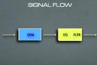
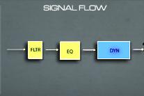
| 1. DYN + EQ
(Dynamics + EQ) Use the DYN + EQ algorithm to ensure that the dynamics section is triggered and based on your input source material, with EQ and Filtering applied after. |
 |
|||||||||||||||||||
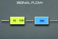
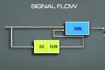
| 2. CH OUT
(Channel Out) Similar to SPLIT + CH OUT but with EQ applied first.
|
 |
|||||||||||||||||||
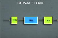
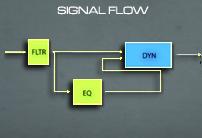
| 3. SPLIT
(Split) Use the 'Split' algorithm to filter the input before triggering the dynamics section. EQ is applied after Dynamics have been applied. The filter is used first in the chain to 'split' out any unwanted frequencies from the upper and/or lower bands. |
 |
|||||||||||||||||||
| 4. SPLIT + CH OUT
(Split + Channel Out) Possibly the simplest of the 6 algorithms as it follows the left-right top-bottom orientation of the effects on the GUI. |
 |
|||||||||||||||||||
| 5. DYN SC
(Dynamics Sidechain) Use this algorithm to obtain that classic Phil Collins gated snare sound. This is called 'frequency conscious' gating, allowing control over the frequency of the sidechain used to trigger the gate. Therefore the engineer will be able to 'hone in' on the attack on the target sound (e.g. Snare) and filter out unwanted frequencies that may inadvertently trigger the gate (e.g. Hi-Hats). |
 |
|||||||||||||||||||
| 6. SPLIT + SC
(Split + Sidechain) Similar to DYN SC except that the Filtered signal is passed through the Dynamics section and on to output (rather than just used for the Side Chain). |
 |
|||||||||||||||||||
Alternatives include the Scope 5.0 bundled SL9000 channel strip and the new improved DAS SL9000, provided free for previous purchasers and offering GUI and sound improvements over the Scope 5.0 bundled version. See screenshot here.
|
|