![]()
|
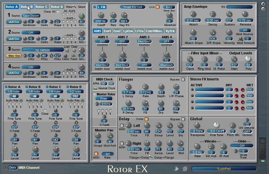
Having read so much about John Bowen Scope synths but not actually owning one until now, I decided the Rotor EX would be a good entry level into the world of Zarg. The accompanying manual was very well written and comprehensive. I also knew that a device with 16 oscillators would need most of my modest 12DSP so I created a dedicated Scope project for browsing the dozens of presets packaged with the device. I was not disappointed. The presets ranged from a few stock pads to the more exotic sound effects and wavestation/wavesequence type transitioning pads. Having briefly read the manual, I decided to start from basics by zeroing out all the oscillators and making a basic saw pad, using one sawtooth oscillator per rotor (adding more later for the benefit of the animated graphic below). The 'tabbed' style parameter selection made this a breeze and made for an ergonomic space saving layout, and I found I was able to create a usable pad sound within an hour of loading Rotor EX for the first time. |
| Rotor-Ex 2 Factory Sounds | Chopper |
Having explored some of the basic concepts of Rotor-Ex, I asked John Bowen if he could enlighten us on some of the design concepts of Rotor-Ex.
![]()
|
Dante: John, your chronicles detail some early R&D work based on a Scope module called 'Rotor'. Could you explain the Scope Rotor, and your intentions of how to add to that functionality ?
John:
The original Rotor device came from an idea by the DSP coder at Creamware,
Klaus Peihl. I'm not sure if he named it, or another guy there (my immediate
boss, Michael Ruf), but the name is derived from the
Wankel Rotary Engine,
of course.
One of the things I wanted to try was to see how it
sounded if I ran the Rotor at audio rates, and tracked the keyboard. The
wavestation can not run the wavesequences at audio rates, and I thought this
might produce interesting results. Dante: Your chronicle outlines the development of the original Rotor in 1999, but it was not adopted commercially at that stage. Can you give us a brief timeline of the Rotor models after this and how they culminated in this latest five Rotor (Rotor Ex) design ? John: This module was in the basic building blocks of the Scope module library, but had not been put into any synthesizer at the time. I had a couple of ideas with it, which were pretty complex, and beyond the interest of my bosses there at Creamware, so I didn't do anything with it until I had left Creamware and was on my own. Dante: So this led to the development of the Rotor 48 ? John: What I thought would be interesting would be to have not one, but four of these rotor objects in one synth, with the outputs of each feeding a fifth 'Master' rotor object. This way you could have very extreme evolving pad sounds, since you could have the four input Rotors slowly cross-fading, and then the Master Rotor also slowly moving across the four Rotor inputs! Of course, this meant a fairly complex layout, since you would have a total of 4 x 4 inputs, and with each input, the choice of being an oscillator, a WAV (sample) playback, or External Input. This is where I got the number '48' for the name of the first plug-in, the Rotor 48, meaning sixteen total inputs, with RD, WAV, or External as inputs. This version was released around March 2001.
Dante: So why was this scaled down to the
Rotor Jr.? Dante: And improvement on these designs as well as a new Creamware 'User Interface Page Control' lead to the Rotor EX? John: These two plug-ins did not sell very well, but I always thought they were unique. After I worked on quite a few other plug-in ideas, I came back to the Rotor 48, to see what I could do to really improve it. This was the Rotor EX, which I released July 2005. This benefited from a new User Interface control that Creamware had added, allowing one to page on the surface of the User Interface, and I was able to get a lot more of the parameters on one surface, and a better layout for everything. I also borrowed some things from my Quantum Wave synth, which was a four-part Waldorf Wave emulation. I brought over the looping envelope and some of the other ideas I had in the QWave, and also developed this idea of using various colors for the little round bussing buttons to provide more modulation routing and flexibility, which I called AMS routing (Alternate Modulation Sources). Here's some explanation from the manual: AMS makes it possible to provide four different modulation paths to each of the synthesizer's 16 oscillators without creating a cumbersome or overly complex user interface. Rather than providing 64 individual modulation sources, each with their own amount, control and source list, AMS uses a generic modulation source and allows the user to simply turn on the modulation destination with a switch. The modulation source, amount, and control source for AMS 1-4 are set at the Cntrl/Misc. page. Each oscillator has a set of buttons that allows you to enable or disable modulation for each AMS source. Each button has several states, which determine the destination of the AMS source. These states are selected by clicking on the button repeatedly until the desired destination is indicated. To make things simpler, color coding is used for destinations:
Holding the mouse cursor over a button will list its destination colors. There is also a ‘Clear All’ button to reset all AMS buttons per each Rotor oscillator group to the OFF position. Dante: So just to re-iterate on the five Rotor design inherited from the Rotor 48, I can see Rotors A, B, C and D on the GUI, they all feed into the fifth master Rotor? John: Yes, the fifth one is the Master Rotor, and it uses the other four Rotors as its inputs. It's primarily to give even more possible variation to long evolving type sounds. |
|||
|
|
|